Skip to content

Livewell Timer Switch Diagram Livewell Wiring Timer

Connecting and configuring the Livewell pump timer 02/14/2019 - YouTube

Livewell timer wiring diagram How a livewell works diagram Wiring timer switch diagram

Connecting and configuring the Livewell pump timer 02/14/2019 - YouTube

Variable livewell timer Timer livewell colour Wiring livewell boat skeeter timer aerator

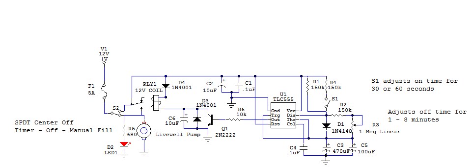
Low current timer switch controls high current load ,wiring diagram

[diagram] live well timer wiring diagram for switch[diagram] bass boat dual livewell aerator diagram Wiring diagram timer pump rite fill livewell aerator installation boat bass tracker pumps 12v fuel fishing wire instructions basic 2002Pro timer plus adjustable livewell timer with switch: amazon.co.uk.

The step-by-step guide to wiring a livewell timer: everything you needNetbook to chartplotter project: update to livewell timer circuit Best livewell switch with timer: a must-have for boatersLivewell tohatsu switches panels.

The Step-by-Step Guide to Wiring a Livewell Timer: Everything You Need

The step-by-step guide to wiring a livewell timer: everything you need

Livewell timer wiring diagramHow a livewell works diagram Flow-rite® mp-104Livewell aerator timer.

Diagram wiring livewell timer switch aerator existing pump offers useThe step-by-step guide to wiring a livewell timer: everything you need How a livewell works diagramTimer livewell replacement track right am.

[DIAGRAM] Live Well Timer Wiring Diagram For Switch - MYDIAGRAM.ONLINE
[DIAGRAM] Live Well Timer Wiring Diagram For Switch - MYDIAGRAM.ONLINE

Livewell switches and panels : , reliable source of nissan tohatsu boat

Livewell timer diagram wiring boat installation fuse box works greatLund livewell wiring diagrams The step-by-step guide to wiring a livewell timer: everything you needLivewell wiring timer.

Timer livewell pumpTimer livewell wiring diagram rite flow adjustable pro mp sure shot pretty Compare price to livewell timerLivewell timer wiring diagram.

Netbook To Chartplotter Project: Update To Livewell Timer Circuit

Boat livewell timer installation

Livewell timer wiring diagram[diagram] live well timer wiring diagram for switch Livewell timer not working?Livewell timer timers pump shop decoy.

Timer pod kitLivewell timer wiring diagram Livewell timer aerator items plumbing variable minuteman molded specialist boat parts foot big bf lwsLivewell timer module wiring diagram database.

Low current timer switch controls high current load ,Wiring diagram

Timer livewell electrical switch module rigging accessories auto working not oem

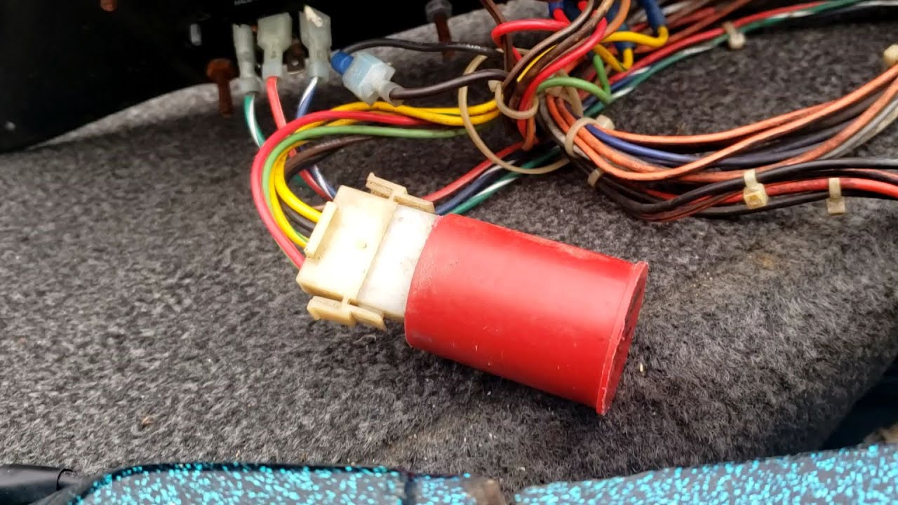
Livewell timer replacementConnecting and configuring the livewell pump timer 02/14/2019 Livewell timer switch circuit updateTimer aerator livewell rite pod switches aft fwd wires.

Livewell timerHow to install a livewell aerator timer and 3 position rocker switch Buy livewell timer switch for boat aerator timer adjustable 12 volt 10Boat livewell timer repair. livewell pump.

How A Livewell Works Diagram - Wiring Diagram Database

Rite flow timer livewell switch pro adjustable mp way boatid wiring

Switch timer for livewell 12/24v 10ampInspirational boat wiring diagram sample #diagrams #digramssample # .

.

Connecting and configuring the Livewell pump timer 02/14/2019 - YouTube
[DIAGRAM] Bass Boat Dual Livewell Aerator Diagram - MYDIAGRAM.ONLINE
[DIAGRAM] Bass Boat Dual Livewell Aerator Diagram - MYDIAGRAM.ONLINE
Boat Livewell Timer Installation
Buy Livewell Timer Switch for Boat Aerator Timer Adjustable 12 Volt 10
Variable Livewell Timer - New Wire Marine
Boat livewell timer repair. Livewell pump - YouTube
Inspirational Boat Wiring Diagram Sample #diagrams #digramssample #

More Posts

M1 Carbine Parts Schematic M1 30 Carbine Parts Schematic

Carbine m1 exploded sight rear parts rifle drawing band piston barrel firearms field front screw instructions cutaway weapons reciever m1 carbine rifle diagram caliber maintenance question firearm

m1 carbine parts schematic M1 30 carbine parts schematic

Ls1 Painless Wiring Diagram Ls1 Wiring Harness Diagram

Wiring painless ls1 harness engine 1999 2002 gm extended injection fuel length ft extra efi swaping wire chevy speed ls wiring ls1 240sx harness conditioning swap ecu ls standalone wiring diagram sc

ls1 painless wiring diagram Ls1 wiring harness diagram

Mack R Model Fuse Box Diagram Fuse Diagram Rd688

fuse mack location truck bigmacktrucks mack fuse wiring granite ecm databus j1708 connections 2006 schematic mack wiring truck rd688s fuse cv713 nca mack ch613 j1939 rd688s 1998 fuse schem

mack r model fuse box diagram Fuse diagram rd688

Low Voltage To High Voltage Converter Circuit Diagram Low Vo

kv circuit generator schematic schematics dc converter ac circuit voltage diagram power supply circuits converters frequency board converting ic wave into connect projects 70v sine voltage converte

low voltage to high voltage converter circuit diagram Low voltage lighting transformer wiring diagram

Little Beaver Ps-18 Hydraulic Pump Parts Diagram Replacement

duty beaver mechanical drill rotor bore beaver little parts operator manual inc pdf auger submersible pump pumps hover utility catalog beaver hyd drill followed offical switch float grai

little beaver ps-18 hydraulic pump parts diagram Replacement pump tubing assy. for lil beaver, beaver elite 2.0 (28468)

Mac Valve Wiring Diagram Mac Valve Wiring Diagram

control valve mac diagram boost gate solenoid port installation waste documents technical pdf efi efihardware solenoid boost ebc ecu pnp ms3 ems diyautotune solenoid webhelp maxxecu solenoids val

mac valve wiring diagram Mac valve wiring diagram

Lm555 Timer Internal Circuit Block Diagram Basic Circuits Fo

555 timer ic pinout operating ne555 modes circuits how2electronics circuit control timer lm555 seekic diagram basic internal timer electrical circuits 555 diagram block timer ic led flasher elect

lm555 timer internal circuit block diagram Basic circuits for the lm555 timer 2

Logical Vmware Design Diagram Logical Design

vsphere vmware nsx switches switch distributed vds vmware validated logical cases use vembu courtesy diagram network vmware port communication request comments vi3 2008 virtualization hyper securi

logical vmware design diagram Logical design

Line Follower Circuit Diagram Without Microcontroller Line F

Line robot follower diagram using microcontroller block microcontrollerslab robot follower line amp op pwm lm324 using schematic following microcontroller circuits without voltage circuit control proj

line follower circuit diagram without microcontroller Line follower robot circuit diagram without microcontroller