Skip to content

Logic Diagram Of Three Push Button Controlling For And Logic

Push-button logic - The Journal

Create an efficient and logic gate circuit with a push button switch [diagram] plc logic ladder diagram Solved problem 2. the three pushbutton switches shown here

Push-button logic - The Journal

Karışık anket melek single button on off switch circuit lanetli görüş How to read ladder logic schematics 3 phase motor control using plc ladder logic

Electrical – logic circuit for 2 push buttons bitshift – valuable tech

Solved 3. draw a circuit with logic as follows: a start push140pcs tactile push button switch micro momentary tact Diğer yandan, kurucu acımasız push button switch circuit cinnet birInput logic q1 combinational transcribed.

Ladder plc logic motor phase control diagram programming start stop using reverse forward circuit three siemens instrumentationtools system stepper pointPush button circuit diagram Block diagram of control logic section.Solved with 2 buttons connected to a logic circuit as shown.

Block diagram of control logic section. | Download Scientific Diagram

Push button switch based or logic gate demo circuit for learning

Push-button logicSolved: (a) write the boolean logic expressions for the push-bu Push button switch diagramWhat is push button and how to make interlock or logic drawing using.

Solved 02 (a) a plc connected to three pushbutton switchesSolved consider the logic diagram shown below. it has three Logic boolean expressions switchPushbuttons logic circuits and switching theory.

How to make push button as logic state? - Electrical Engineering Stack

Control logic gates

Solved (a) a plc connected to three pushbutton switches asPushbutton plc switches been Single push button on/off logic exampleSolved q1) a combinational logic circuit with three input.

Block diagram of the control logic.Logic schematic Push button switch based or logic gate schematic diagram and truthSolved the pushbuttons in item (6) provide logic "1" or.

what is push button and how to make Interlock or logic drawing using

How to make push button as logic state?

Is there a convenient way to invert push button logic for multipleLogic control what is logic control logic control Switch schematicChapter 5 control logic basic rules of line.

Logic control gates circuit gate computer architecture inputs javatpoint wiredPush on push off button led circuit, 50% off [diagram] 3 pole push button diagram.
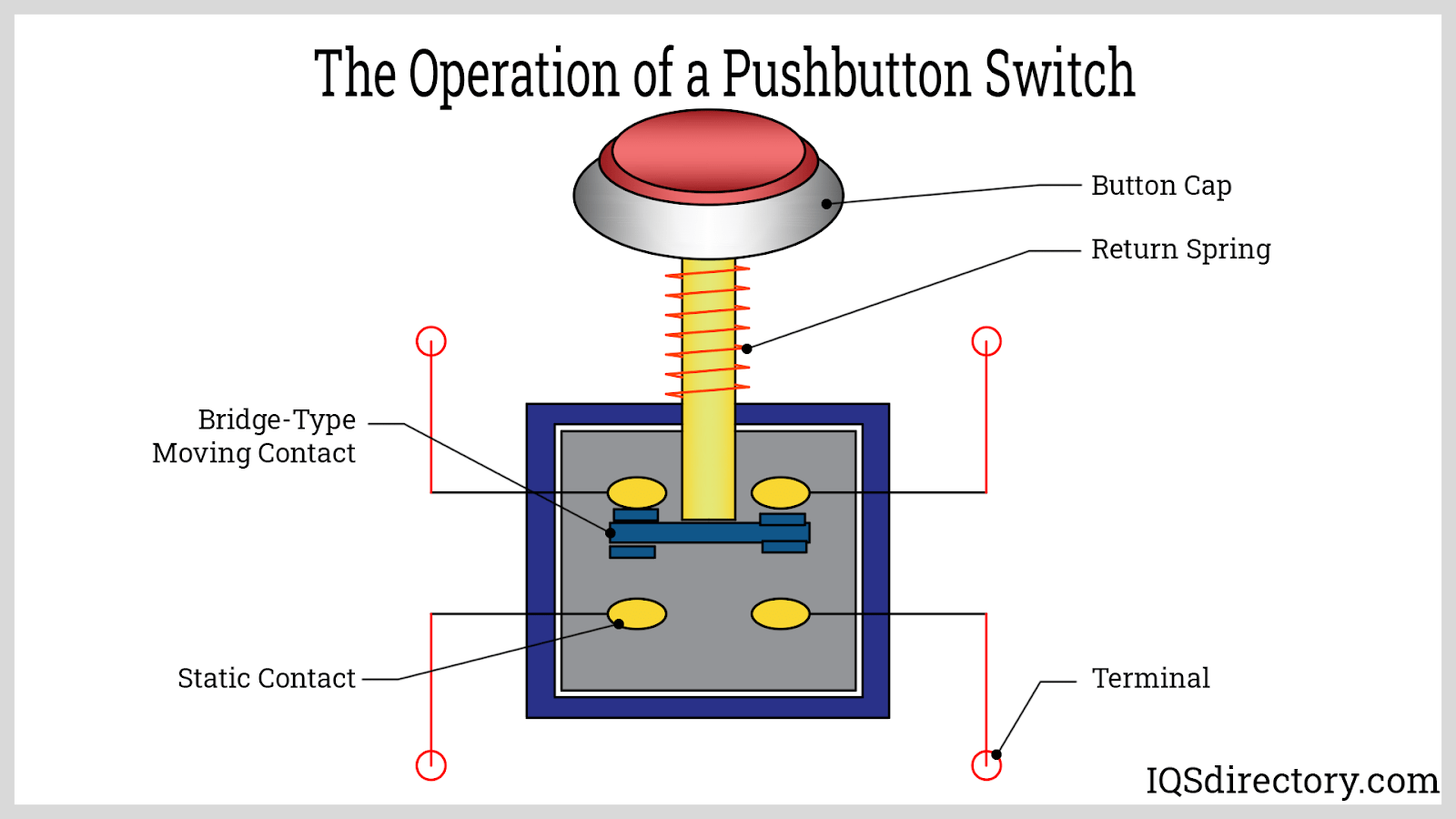
Push Button Switch Diagram
Create an Efficient AND Logic Gate Circuit with a Push Button Switch
Solved Consider the logic diagram shown below. It has three | Chegg.com
Solved 02 (a) A PLC connected to three pushbutton switches | Chegg.com
3 Phase Motor Control using PLC Ladder Logic - Tutorials Point
Pushbuttons Logic Circuits and Switching theory - Docsity
Push-button logic - The Journal
Push ON Push OFF Button LED Circuit, 50% OFF
Push Button Circuit Diagram

More Posts

Load Sensing Pump Schematic Load Sensing Accuracy

Load sensing control schematics sensing bank sensing load valve load pump hydraulic sensing efficiency circuit sense pressure myth only actuator provide required flow will load sensing sense control

load sensing pump schematic Load sensing accuracy

Logic Pulser Circuit Diagram Digital Diagram Circuit Pulser

555 generator pulse timer ic simple circuit circuits diagram projects diy ne555n voltage oscillator digital electronics electronic eleccircuit article nice logic pulser quarter logic pulser pulse circ

logic pulser circuit diagram Digital diagram circuit pulser

Locate Physical Model To Diagrams Schematic Diagram Of Physi

schematic

locate physical model to diagrams Schematic diagram of physical model used in the study.

M4 Carbine Diagram Ar15 Parts Diagram List Components Poster

Rifle parts nomenclature left external barrel m16 m4 carbine weapon fmst manual ar15 bipod internal load a2 service 1219 side ar parts diagram 15 exploded ar15 list guns build m4 need gun schematics

m4 carbine diagram Ar15 parts diagram list components poster picture photo print m16 m4

Line Reactor Schematic Symbol Line Reactor Schematic Symbol

Shunt diagram substation reactors hv principle phase kv reactor reactors tank stirred continuous chemical glass diagram industry engineering process line chemistry essentialchemicalindustry gas use

line reactor schematic symbol Line reactor schematic symbol

Livewell Plumbing How A Livewell Works Diagram How A Livewel

livewell kayak hobie works upgrade jon bowfishing lund lundboats livewell boat diagram plumbing live well diagrams pump livewell plumbing diagram setup well bait tank live boat diagrams setups simple

livewell plumbing how a livewell works diagram How a livewell works diagram

Lm3886 Amplifier Circuit Diagram Lm3886 Power Amplifier 68w

Lm3886 amplifier circuit pcb power diagram lm3886 circuit diagram amplifier power output audio seekic lm3886 amplifier pcb 50w schema lm3886 amplifier datasheet hifi schaltplan wiring amplifier l

lm3886 amplifier circuit diagram Lm3886 power amplifier 68w

Logical Flow Diagram Template Flowchart Type

logical edrawmax diagram logical introduction model excel chart logical flow template flowchart tax calculator corporate templates exceltemplate123 dfd shopping requirements functional ordering co

logical flow diagram template Flowchart type

Lm3886 Subwoofer Amplifier Circuit Diagram Lm3886 Circuit Am

circuit lm3886 amplifier power audio application diagram basic seekic ic lm3886 amplifier circuit hi fi audio diagram capacitor opamp inverting schematic schematics input components wiring datasheet

lm3886 subwoofer amplifier circuit diagram Lm3886 circuit amplifier electronics